trim tab switch wiring diagram
Operation and Installation Manual. Linear Devices Corporation dba Lectrotab. Ashland, VA 23005 www.lectrotab.com Phone: 804-368-8428 Fax: 804-368-8438.

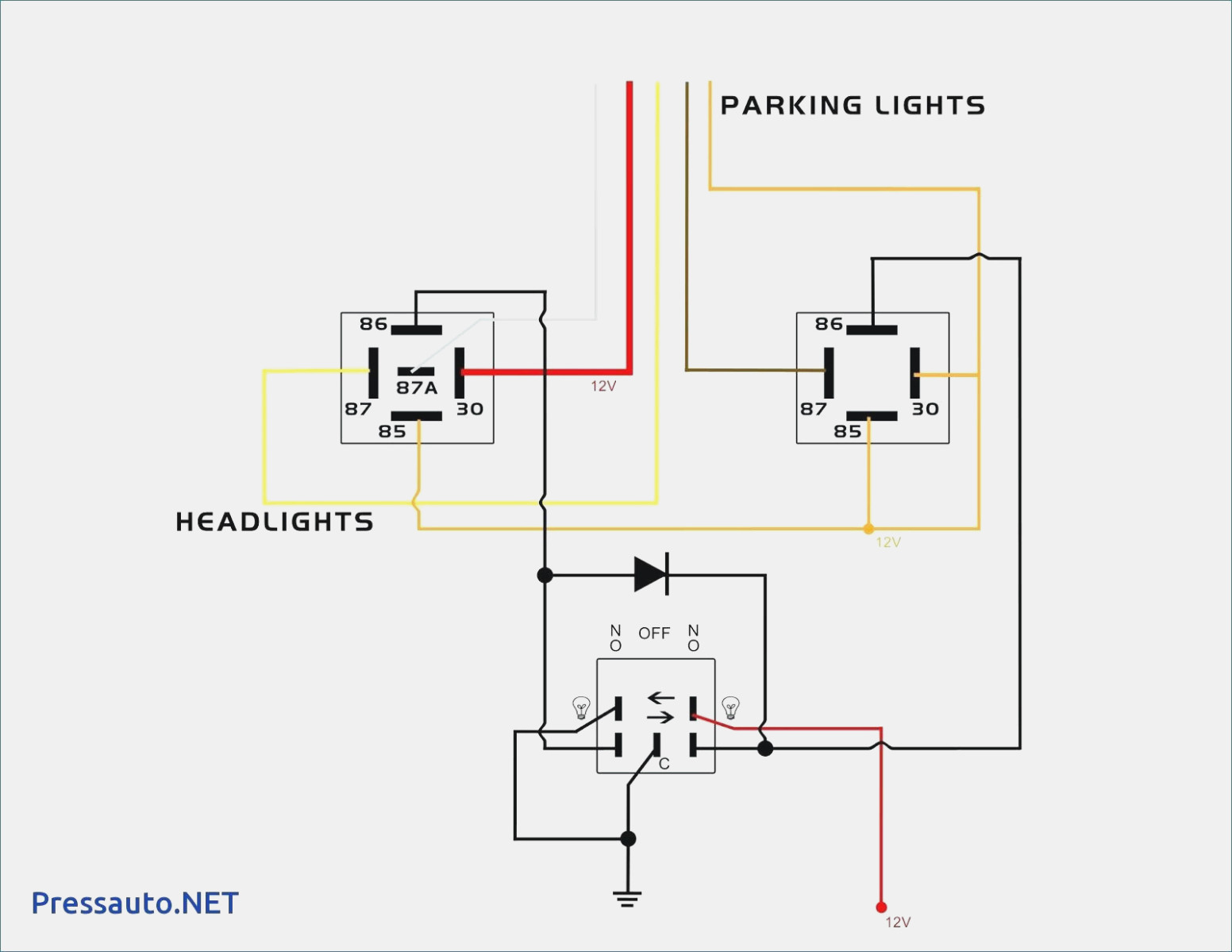
Trim Tab Switch Wiring Diagram Light Switch Wiring Diagram
The Benefits of Trim Tabs Increase Visibility For A Safer Ride:Keeping your bow down at reduced speeds is important, especially in congested waters or foul weather. Bennett trim tabs enable you to plane at a much lower speed, operating your boat more safely.
Lenco Trim Tab Switch Wiring Diagram Wiring Diagram Schemas
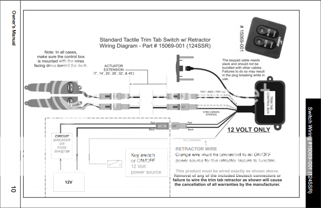
per the diagram below. console. 3) Test the trim tabs for proper operation. that the right switch controls the left trim tab and the left controls the right. Bow down should extend the tabs while bow up should retract them. If for some reason this does not work as described in the above text then recheck all the wiring for a misplaced wire.
lenco trim tabs wiring diagram
Trim tab switch wiring is an essential component of trim tab systems, which are used to adjust the position of boat or ship fins to optimize stability and control. Understanding the basics of trim tab switch wiring is crucial for properly installing and operating these systems.
Lenco Trim Tab Switch Wiring Diagram
Depending on your tab model, if equipped with an electric sensor, only drill one hole for the wire access thru the transom. Mount the tab: If the Livorsi Trim Tabs are replacing existing tabs, make sure to seal any unnecessary holes on the transom. Use a high quality marine sealer suitable for underwater use.
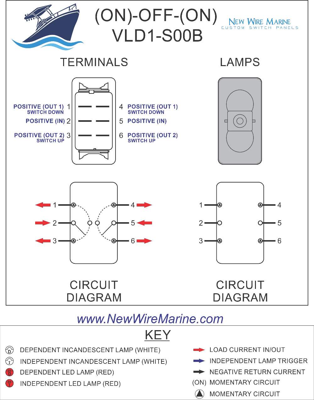
Trim Tabs Rocker Switch Carling Contura II Illuminated Accessory
Diagram # Description Part # 1 Fluid Reservoir VP1139 2 #10 x 1" Philip Pan Head Sheet Metal Screw H1180. 33 Euro-Style Rocker Switch Control ES2000 34 20 Amp Fuse (12 volt system) H1176 35 Fuse Holder H1178. (Red wire operates port trim tab; green wire operates starboard trim tab).

Lenco Trim Tab Wiring Diagram Easy Wiring
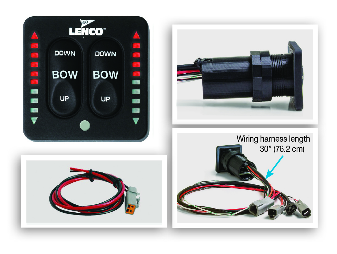
trim tabs, use short momentary taps of the switch. To become knowledgeable on how your boat performs with Lenco Trim Tabs, remember, practice makes perfect. When the tabs are lowered, the water flow is redirected, creating an upward force at the stern of the boat. Without Trim Tabs With Trim Tabs TRIM TAB OVERVIEW SWITCH OVERVIEW
Lenco Trim Tab Switch Wiring Diagram / How To Fix Upgrade Trim Tabs Part 1 Youtube Lenco trim
Product Description Backlit Rocker Switch - Trim Tabs This genuine Carling rocker switch labeled "Trim Tabs" is manufactured by laser marking, NOT printing. Laser technology allows for a stunning backlight effect. It is a great upgrade to our popular Contura II style Trim Tabs rocker switch.
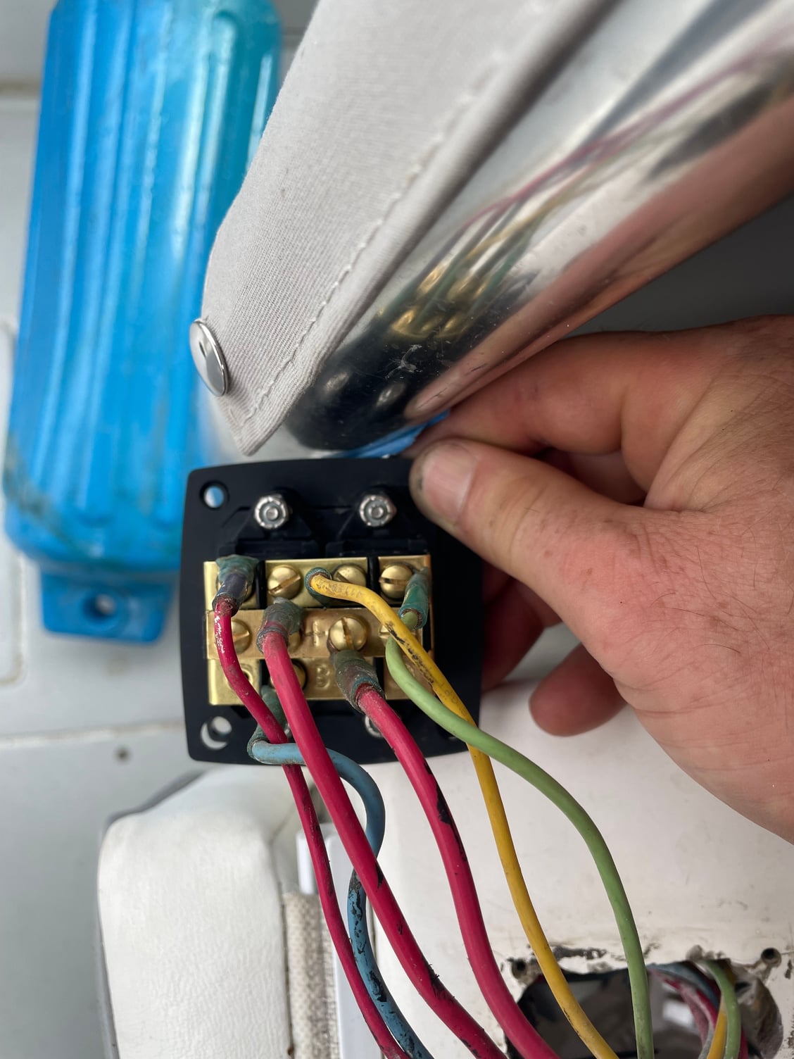
ES2000 Trim Tab Switch Wiring on Contender The Hull Truth Boating and Fishing Forum
Connect the orange wire from the rocker switch to (+) 12V Check carefully ensure there are no obstructions behind the (20A) power and black wire to ground. console before drilling. Using a 2.5" diameter hole-saw, drill the center hole. Use a 7/64" drill for the four mounting stud holes. Unsnap the bezel from the control plate.
Trim Tabs Wiring Diagram Wiringonus
The wiring diagram provides a visual representation of how the trim tabs should be wired to the control switches and power source. The Lenco trim tabs wiring diagram typically includes the following components and connections: Trim tab motors: These are the motors that control the movement of the trim tabs.
Lenco Trim Tabs Wiring
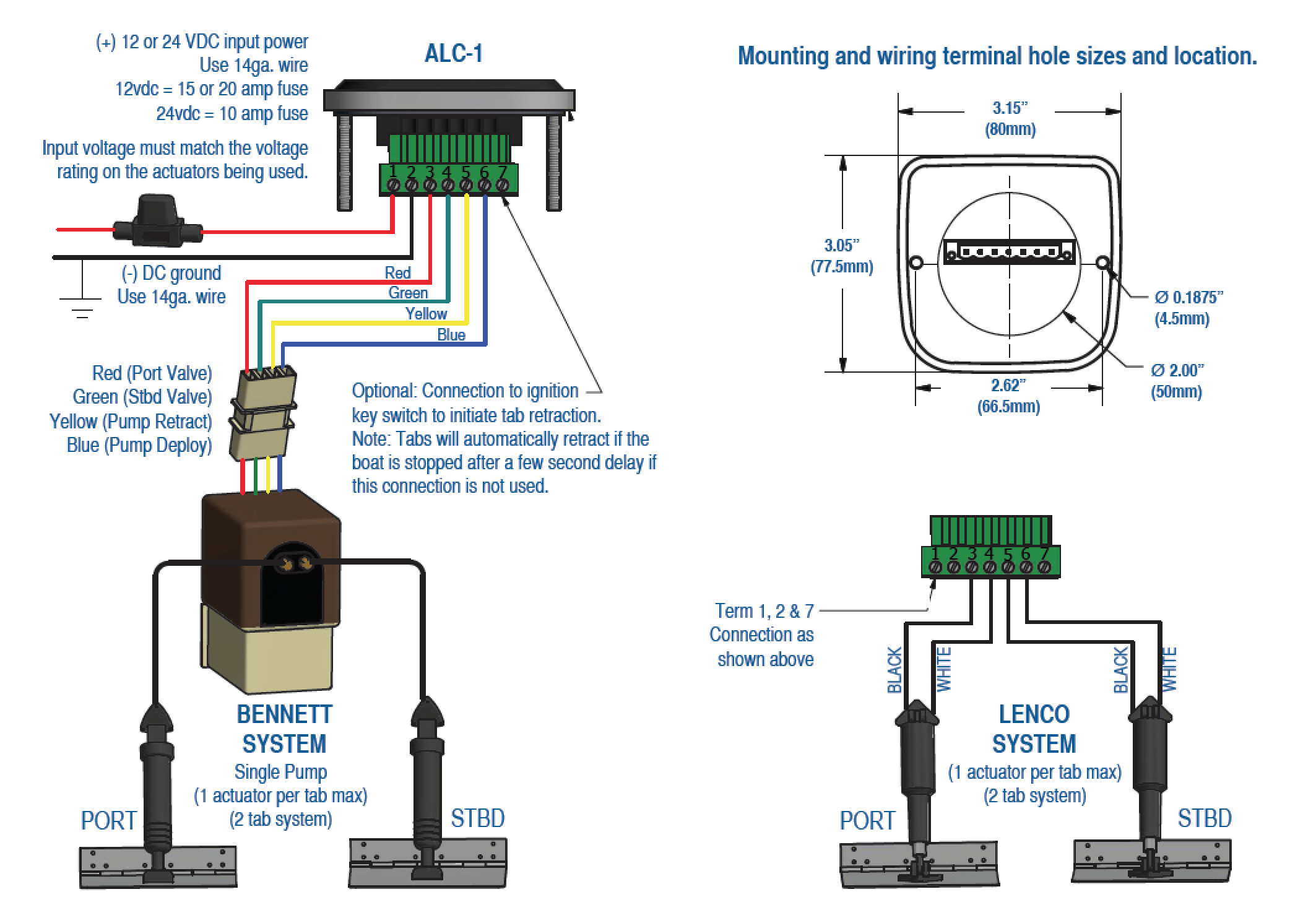
Wiring Diagrams | Lectrotab Electromechanical Trim Tab Systems Joystick LED Control (JLC-11) Flat Rocker Switch (SAF-SC and SAF-NSC) One-Touch LED (SLC-11) Manual Leveling Control (MLC-1) Auto Leveling Control (ALC-1) Auto Leveling Control (ALC-1D/2D) NMEA 2000 Connection to SLC One-Touch LED Control Discontinued: Oval Control (SETR-61)
Lenco Trim Tab Switch Wiring Diagram Wiring Diagram Schemas
LED. Trim Tab Indicator Switch w/ Retractor and Self-Check Wiring Diagram - Part # 15070-001 (123SC) Note: In all cases, make sure the control box is mounted with the wires facing down toward the deck. CIRCUIT BREAKER OR FUSE 20A@12V IOA@24V 12V OR 24V ACTUATOR EXTENSION (7', 14', 20', 26', 32', & 45') Black The keypad cable needs
Lenco Trim Tab Switch Wiring Diagram Wiring Diagram Schemas
Have questions? We're here to help. Visit BennettTrimTabs.com or call (954)427-1400. Wiring Diagram Ground (Black) (Purple) ATR/Ignition Power Helm Power (Thicker Orange, or Red) 6 ft. (Orange) 3 ft. 3 ft. Twisted Extension Cable (Variable Length) 6 ft. Actuators & Tabs
Trim Tab Switch Wiring Diagram Unity Wiring
1. Adjust the trim tabs to achieve a planing attitude. 2. Use the power trim to position the prop path parallel to the water flow as indicated by increased RPM / Speed. 3. If necessary, re-adjust the trim tabs to fine tune the trim of your boat. In other words, use your trim tabs to trim the boat and your power trim to trim your prop.

Trim Tab Switch Wiring Diagram Light Switch Wiring Diagram
Lectrotab trim tabs improve fuel efficiency, increase boat speed, accelerate shallow water planing, eliminate porpoising, and enhance the overall boating experience with a more comfortable ride. Improved Fuel Efficiency and Faster Speeds Most importantly, the trim tabs may be adjusted to optimize speed and fuel efficiency.
HELP!!! Lenco Trim Tab installation. The Hull Truth Boating and Fishing Forum
Use your trim tab rocker switch with caution. For best maneuverability, trim tabs should be fully retracted in a following sea or when running an inlet. Improper use of trim tabs can cause accident or injury; make periodic checks of hydraulic lines, switches, wiring and fluid levels, looking for corrosion, fatigue and proper oil levels.